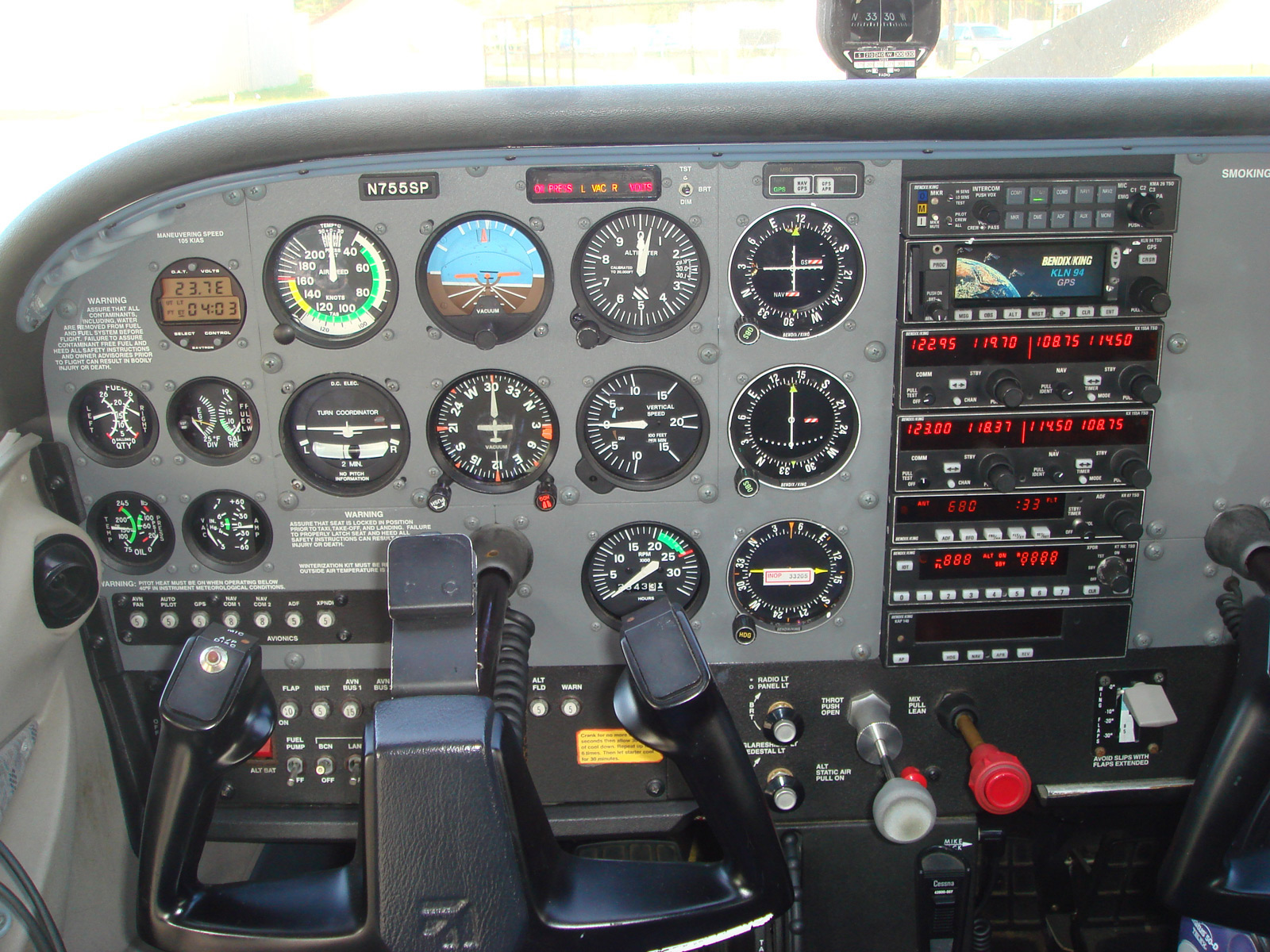
When I first set out to make this annunciator, I wanted to make it look exactly like it does in X-Plane. During development I realized that the X-Plane annunciator does not look or function like the real thing at all. The sim version has 8 indicators: Generator, Battery, Fuel Quantity, Parking Brakes, Oil Pressure, Oil Temperature, Low vacuum and Autopilot disconnect. With the engine stopped and both alternator and battery switches on, only the generator indicator is on. I may not understand what the low vacuum or oil pressure indicators are supposed to mean, but it seems that with no engine running, there shouldn't be any vacuum or oil pressure. I decided to model my annunciator on the real thing. I found a bunch of pictures online of an actual cessna 172 cabin and found it only had a few indicators on it. Here's
one such picture showing the bottom row of indicators illuminated: Oil Press, Left and Right Vaccum and Volts. Using
this resource on cessna instruments, I was able to discern the top row that indicates low fuel level on both left and right tanks. Thankfully the real annunciator has 8 indicators as well since the left and right indicators just have an L and R light next to the name of the indicator. This means I can use the same hardware as the original design built to mimic the simulator's annunciator. The lights are as follows: L, Low Fuel, R, Oil Press, L, Vac, R, Volts.
My next hurdle after designing the firmware was to drive it correctly. X-Plane does offer some datarefs for the annunciators, but they don't always work correctly. I, instead, read the raw values that the indicator would be concerned about and if that is at a value that would illuminate the indicator, I light it up. I've made sure to check if there is actually bus voltage as well, so that no indicators will light if there isn't any electricity on the bus. Using my method, I can follow the cessna 172 startup checklist to a T! awesome.
Here's a picture of my prototype on a breadboard:
It's a very basic circuit consisting of a PIC18F4550 configured to work as a USB device, the connector for programming it, 2 input buttons that will be connected to a single switch with three modes( test, brt, dim), and output to 8 LEDs. For the finished product I'll have more LEDs depending on how big the text I'm trying to illuminate is which means I may have to add some transistors. Once I get the hardware more fleshed out I'll be able to do some tests with lighting.
Stay tuned for the results of my milling adventures to make the front glass and the light fence in back.

No comments:
Post a Comment